
Originally written: Aug 2006
Last year’s devastating hurricanes and flooding in the Gulf Region created an overwhelming need for housing for all those whose homes were destroyed. Eyewitnesses still report that it appears as if the damage was done only just yesterday. The clean-up and re-building job is so huge that all the work done to date seems to be almost insignificant. Recently, in order to help, I have been working on some designs for all types of residential units in all parts of a vast region.
SIPs have a great deal to offer in this resurrection effort. ............
SIPs have a great deal to offer in this resurrection effort. ............
They deliver superior product by virtually every metric utilized in assessing construction value, and promise to meet the new set of higher expectations for buildings that have become part of our bundle of programmatic requirements for new construction. Since we have seen the unbelievably extensive damage caused by water and moisture to “conventional” construction, the ability for SIPs to “take a wetting without much fretting” – especially those with cementitious, metal, or composite skins – places them at the top of the list as the material of choice for this huge job. Further, their superior structural performance under high wind conditions without the need for all that remedial steel strapping that stick construction requires reinforces the selection of SIPs for construction in the Gulf States.
Of particular interest to me is the issue of eave design. At first it would seem that the best strategy would be to cut any and all roof overhangs back to virtually flush, after all, one sees many indigenous buildings constructed this way in my native northeast. We are a rather windy region compared to most of the United States; therefore consideration of the wind uplift resistance issue together with a detail that tends to resist ice-damming has much to recommend it. But we are not building in the northeast and the best architecture always thoughtfully responds to the issues of Time and Place. In the southeastern sections of our country a different set of issues has to be recognized and dealt with – both climatically and otherwise.
The obvious short list goes like this:
1. Wind uplift resistance necessitated by many severe and frequent hurricanes.
2. Water resistance necessitated by many severe and frequent hurricanes.
3. Mold and mildew resistance caused by the prevailing high humidity and temperatures.
4. Flood surge resistance.
5. Wind uplift resistance.
Oh, and did I mention:
6. Wind uplift resistance?
A good building is a refined, nuanced, and balanced response to a long list of traditional climactic, material, economic and cultural requirements. The Standard Franchised Fast Food Restaurant Chain Buildings plunked down identically all over the country irrespective of variations in locale is a textbook example of poor design and building. On our list must also be a very important item; one addressed by the size of the roof overhang: solar shading.
On Long Island, where I usually practice, is a region where our heating season is conventionally construed to last for over 7 months of the year; however over 87% of all new homes are constructed with air-conditioning. This is because we also experience hot and humid summers -- and don’t even think about getting me started on Global Warming! Unlike my part of New York, air-conditioning in much of the south may be conventionally “required” for over 10 months of the year. And what power source do we utilize to bring us this miracle of climate control?
Electricity.
Here’s the story. While mechanical engineers have made absolutely terrific strides in improving the efficiency of air-conditioning systems of all types, they all work essentially the same way by moving heat from the inside of the building to somewhere outside the building, usually to air or water. Unlike boilers and furnaces which convert fuel into heat energy, air-conditioning requires fuel (electrical energy) to operate motors that move existing heat energy from one place to another, from the inside of your insulated refrigerator to the coils on the back where it is dissipated into the room, or from the inside of your home to the coil and fan unit outside where it is “released” into the ambient air. All this happens with electric motors which convert electrical energy into mechanical energy with very high efficiency, usually well in excess of 90%. In fact, virtually all the electrical devices and appliances in one’s home are pretty darned efficient, with conversion efficiency of 100% for devices like a toaster oven that convert electrical energy into heat energy.
That’s on the home-owner’s side of the wall receptacle. The Dirty Little Secret of the Electrical Industry is that the efficiency of the electrical generation and distribution system that brings the juice to the home-owner’s receptacle is only 30%! That’s the whole system rate, from coal or oil at the central power station to your wall. So in the south, where 80% of home energy bills are for electricity to run air-conditioners, the responsible architect/designer/engineer will do pretty much everything he or she can to reduce the building’s need for air-conditioning. By contrast, for heating a house, some sealed-combustion condensing boilers can convert gas to heat energy with efficiencies in excess of 90%. Understanding these dynamics encourages one to think twice before reflexively electing to establish large scale central electric production plants. In fact the most revolutionary aspect of the “Alternate Energy” or “Clean Renewable” energy movement may be the conversion of the central power production paradigm to the “Distributed Power Production” system. Let’s go back to our single home example and look at the effect of installing a photo-voltaic system on the roof of the building. Now the receptacle of the house is powered with electricity produced and fed to your panel box with virtually zero transmission losses. Every watt used in the house produced by on site PV (photovoltaics) or wind turbines offsets the production of 3 watts of electricity produced by the Central Power Company. So again, cutting A/C loads is a powerfully correct and important thing to do.
Originally written: Aug 2006
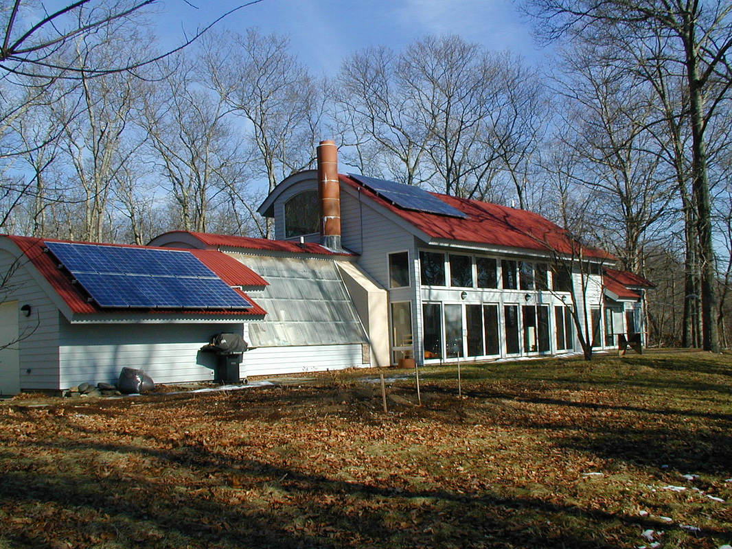
My Long Island New York home with overhangs that provide 100% shading of south-facing glass on the summer solstice. A Southern home might have larger overhangs that provide 100% shading for 6 months or longer.
Oh yes, the building eave, the roof overhang!
We started out making sure we had wind up-lift resistance all over our short list of programmatic requirements for our Gulf Coast house design. Uplift forces are Building Code Specified, with square foot values listed and tabulated according to locale, roof pitch, and location on the roof. Roof corners experience the greatest forces, roof edges next, and central fields the least. The highest values are in the 50 lbs/sq. ft. range, the lowest are about 10. When we document uplift resistance calculations for Code Compliance, we ignore the lower edge and field values in order to be conservative and apply a larger safety factor. This “over-engineering” has an extremely modest cost – just some additional screws – so we believe it to be a cost-effective way to deliver additional cheap insurance.
Let’s take an example…..
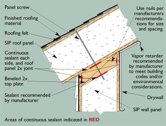
Panel screws have a minimum withdrawal resistance of 600 pounds each without additional washers under the screw head. Where this SIPA illustration shows nails fastening the wall top plate to the wall SIP skins, we always specify screws.
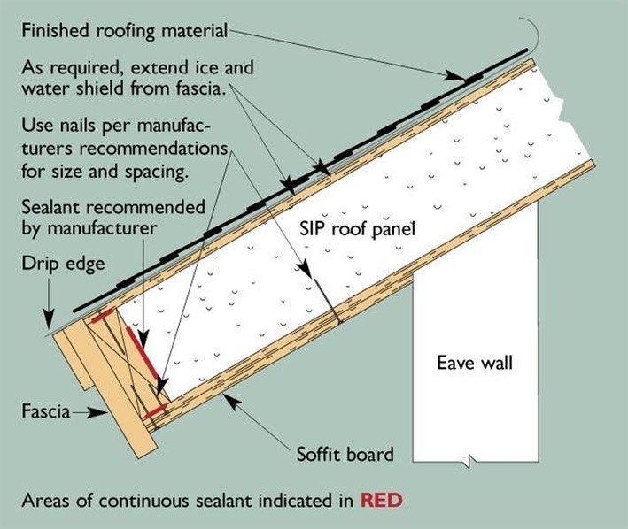
Roof overhangs are most simply created as shown in this SIPA illustration. Other variations would have lookouts creating a level Soffit, or fascia work being set plumb to a factory pre-cut beveled edge with routing ready to receive field-applied blocking.
A simple Shotgun Vernacular home might have a footprint with a 16 foot width and a length of 52 feet for a total of 832 gross square feet. With an 8/12 roof pitch the actual roof area – with no roof overhang is 1.2 times the footprint for a total of 998.4 sq. ft. We’ll call it 1000. If we add a 16” overhang (plan dimension) all around this translates to almost another 200 sq. ft., or a 20% increase!
But wait! There’s more……
Not only are eaves subject to negative pressure fromm the top, but also receive positive pressure from below. The soffit may follow the roof pitch for the 200 square feet noted above, or be level, for an area of 185 sq. ft. Let’s take this pressure to also be 50 lbs/sq. ft.
So the total wind uplift force calculates out as follows….
square feet of developed roof area………………………………………………………..…..1000
square feet of developed overhang area……………………………………………………….200
square feet of developed soffit area……………………………………………………….....…185
---------------------------------------------------------------------------------------------------------------------------
Total area in square feet………………………………………………………………………..1385
1385 sq. ft. x 50 lbs/sq. ft. = 69,250 lbs. Total Uplift Force on Entire Roof
Now we divide this by the total perimeter of the building which is equal to the total length of our SIP walls: 69,250 / 16+16+52+52 = 510 lbs. per linear foot uplift.
SIP screws without washers are rated for over 600 pounds withdrawal resistance; we may therefore specify one per foot to hold the roof down. We have a default minimum specification of 8” On Center, which we would adhere to accounting for that bent one, or the one that hit a split or some other fault in the top plate. The top plate is specified to be fastened with No8 x 1 5/8” screws from both sides, as is the bottom plate. These are each rated for over 140 lbs shear resistance. Therefore: 510 / 140 = 3.64 or 4 screws per foot, 6” O.C. inside and out. There’s the job done with no strapping and a screw spacing pretty much equal to most manufacturer’s minimum specification for proper assembly. This is with a 38.5% increase in uplift loads due to a 16” overhang.
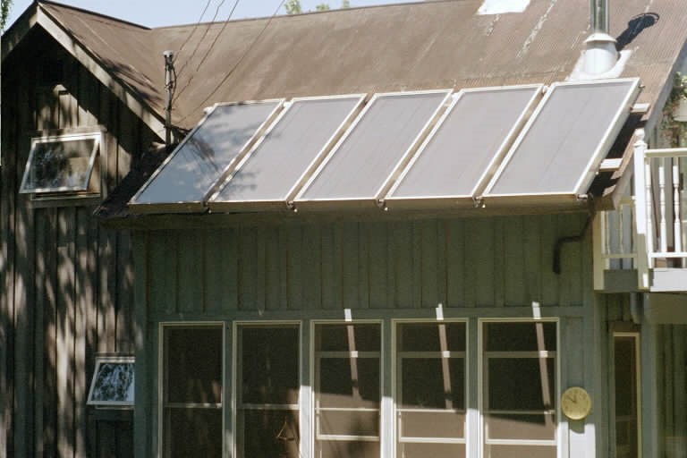
Large overhangs supporting a solar domestic hot water collector array which probably adds about 7 lbs per square foot additional load.
Most SIP manufacturers automatically approve overhangs of 24” true developed length. Bending loads may actually be slightly reduced on the main span from ridge to eave as a result of a significant overhang, but I have yet to see any engineering data from any manufacturer other than load/span tables for single simple spans. Cantilevers may be calculated by using the formulae in the American Plywood Design Supplement covering foam core sandwich panels. Contact the APA technical folks at: www.apawood.org for assistance in this department, or steer your engineer or architect their way. Large overhangs of 4 feet or greater may be designed with internal structural splines.
In the southern latitudes where air-conditioning loads far out-weigh heating loads, overhang projections should be maximized and glass specifications written for a high shading coefficient in order to get those A/C loads down! For the example cited here, proper overhangs may contribute to the downsizing of the HVAC for the example cited here from ½ to a full ton of cooling capacity. This could translate to a front end savings of $1500 or more with smaller ducts as well as smaller mechanical equipment.
SIPs are the foundation for an integrated design strategy incorporating a series of technologies and materials that maximize comfort and livability performance while minimizing operating and maintenance costs. The eaves of a building are far more than a decorative non-essential flourish. Their proper design has great impact on performance of the building as well, of course, as the appearance of the building. The proper engineering and construction of the eave involves mindful consideration of all wind loads as well as gravity loads. Large overhangs poorly conceived and executed may turn into Eaves of Destruction while an appropriate eave detail will deliver increased comfort and energy savings for the life of the structure.
Originally written: Aug 2006
 RSS Feed